TM 10-4320-344-24
e .
f .
g .
Repeat step d until all rings (Figure 4-25, 9) have been checked. The correct
gap dimensions should be as listed in Table 4-10.
Table 4-10. Gap Dimensions.
Dimension
Minimum
Maximum
1st ring gap
0.0177 inches (0.450 mm)
0.0315 inches (0.800 mm)
2nd ring gap
0.0177 inches (0.450 mm)
0.0315 inches (0.800 mm)
3rd ring gap
0.0197 inches (0.500 mm)
0.0315 inches (0.800 mm)
4th ring gap
0.0157 inches (0.400 mm)
0.0315 inches (0.800 mm)
Inspect piston pin (3) for burrs, discolorations, wear, or damage. Inspect
p i s t o n p i n ( 3 ) d i a m e t e r f o r t h e f o l l o w i n g d i m e n s i o n : 1 . 3 7 8 0 i n c h es
(34.994-35.000 mm) on Model 609-C and 1.5746-1.5748 inches (39.994-40.000 mm)
on Model US636HCCD-1.
Inspect connecting rod (4) for straightness and visible damage.
h.
i .
j .
k.
l .
m.
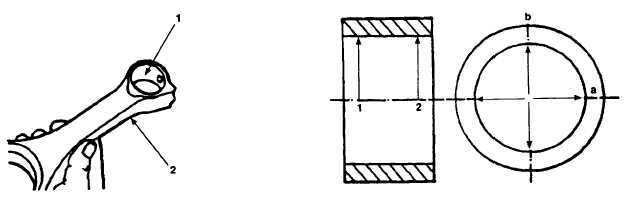
Figure 4-27. Piston Pin Measuring Locations, Models 609-C and US636HCCD-1.
Inspect piston pin bushing (Figure 4-27, 1) for burrs, worn spots, and
discoloration. Measure inside diameter of piston pin bushing (1) at points 1
and 2 in planes a and b, as shown in Figure 4-27. ‘The correct measurement is
1.3795-1.3813 inches (35.040-35.086 mm) for Model 609-C and 1.5764-1.6079
inches (40.040-40.084 mm) for Model US636HCCD-1.
Remove any worn piston pin bushing (1) and press in new piston pin bushing
(1). Ensure oil holes are aligned between piston pin bushing (1) and
connecting rod (2).
Position connecting rod cap (Figure 4-25, 6) on connecting rod (4) and secure
with two cap screws (5). Torque cap screws to 22 ft-lbs (30 N•m).
Using angle-of-turn indicator, tighten cap screws (5) 60° first stage, then
30° second stage.
Measure inside diameter of connecting rod bearing bore at points 1 and 2 in
the planes of a and b as shown in Figure 4-27. The correct measurement is
2.5197-2.5204 inches (64.000-64.019 mm) for Model 609-C and 2.7559-2.7567
inches (70.000-70.019 mm) for Model US636HCCD-1.
Remove two cap screws (Figure 4-25, 5) and connecting rod cap (6) from
connecting rod (4).
4-53