TM 10-4320-344-24
4.4.15 Piston and Connecting Rod Assembly Maintenance, Models 609-C and US636HCCD-1.
This task covers:
4.4.15.1 Removal
4 .
4 .1 5 . 3 I n s t a l l a t i on
4 .
4 .1 5 . 2 R e p a ir
INITIAL SETUP
Tools
General Mechanic’s Automotive Tool Kit,
Appendix B, Section III, Item 1
Angle-of-Turn Indicator, Appendix B,
Section III, Item 3
Arbor Press, Appendix B, Section III,
Item 3
Inside Micrometer, Appendix B, Section
III, Item 3
Micrometer, Appendix B, Section III,
Item 3
Piston Ring Gauge, Appendix B, Section
III, Item 30
Piston Heater, Appendix B, Section III,
Item 31
4.4.15.1 Removal.
Material/Parts
Engine Assembly Grease, Appendix C
Item 13
Oil, Appendix C, Item 15
Rags, Appendix C, Item 20
Tags, Appendix C, Item 31
Piston Rings (TM 10-4320-344-24P)
Equipment Conditions
Oil Pan Assembly removed, paragraph
3 .
8 .
1
2.
Cylinder removed, paragraph 4.4.3.
General Safety Instructions
Use extreme caution when handling heated
components. Heated components can cause
severe burns.
Do not work on equipment without follow-
ing standard shop safety practices.
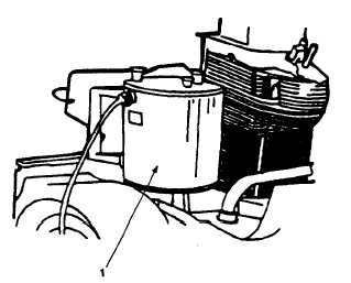
Figure 4-24. Piston Heater Installation, Models 609-C and US636HCCD-1.
4-50