TM 10-4320-344-24
Table 4-8. Piston Ring Dimensions.
Dimension
Minimum
Maximum
Clearance in groove -
Keystone taper
top
Clearance in groove -
0.0040 inches (0.1016 mm)
0.0060 inches (0.1524 mm)
2nd
Clearance in groove -
0.0015 inches (0.0381 mm)
0.0030 inches (0.0762 mm)
o i l c o n t r ol
4.4.14.4 Assembly.
a .
Place upper end of connecting rod (12) between piston pin bosses in piston
(10), and in line with piston pin holes in piston (10).
b .
Slide piston pin (9) into place.
c .
Install two piston pin retaining rings (8).
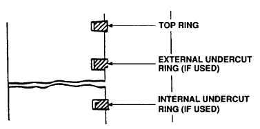
Figure 4-21. Piston Ring Positioning, Model 609-A.
Do not spread rings anymore than necessary to slip them over piston. Rings
could be over-stressed and break.
If piston rings have undercut grooves on outside diameter of ring,
place undercut or groove facing toward bottom of piston. (Reference
Figure 4-21)
If piston rings have undercut grooves on inside diameter of ring,
place undercut or groove facing toward top of piston. (Reference
Figure 4-21)
d.
Using expander tool, install four piston rings (Figure 4-19, 4, 5, 6, and 7)
on each piston (10). Stagger positions of gaps on piston rings (4, 5, 6, and
7) around piston (10) to minimize compression loss. No two gaps of piston
rings (4, 5, 6, and 7) should be in line.
e .
Repeat steps a through d for five remaining piston and connecting rod
assemblies.
4-47
NOTE


