4.4.8 Idler Gear Maintenance, Models 609-C and US636HCCD-1.
This task covers:
4.4.8.1 Removal
4 .4 . 8 . 3 I n s t a l l a t i o n
4 .4 . 8 . 2 R e p a i r
INITIAL SETUP
Tools
General Mechanic’s Automotive Tool Kit,
Appendix B, Section III, Item 1
Goggles, Industrial, Appendix B,
Section III, Item 2
Gun, Air Blow, Appendix B, Section III,
Item 2
Torque Wrench, Appendix B, Section, III,
Item 2
Angle-of-Turn Indicator, Appendix B,
Section III, Item 3
Micrometer,
Appendix B, Section III,
Item 3
Material/Parts
Gloves, Appendix C, Item 11
Material/Parts (Continued)
Rags, Appendix C, Item 20
Solvent, Dry Cleaning, Appendix C,
Item 26
Bearing Sleeve (TM 10-4320-344-24P)
Bushing Sleeve (TM 10-4320-344-24P)
Equipment Conditions
Oil Pump Assembly and Oil Pipe removed,
paragraph 4.4.7.
General Safety Instructions
Do not work on equipment that is not
securely stabilized to prevent rolling
o r s l i d i n g .
Do not work on equipment without follow-
ing standard shop safety practices.
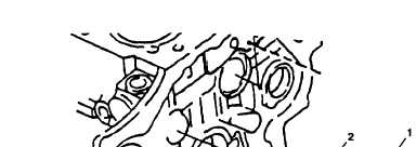
4.4.8.1 Removal.
Remove idler gear (Figure 4-12, 1), sleeve bushing (2), bearing
j o u r n a l ( 3 ), and sleeve bushing (4).
Discard sleeve bushings (2 and 4).
Figure 4-12.
Idler Car Replacement, Models 609-C and US636HCCD-1.
4-28
TM 10-4320-344-24