TM 10-4320-344-24
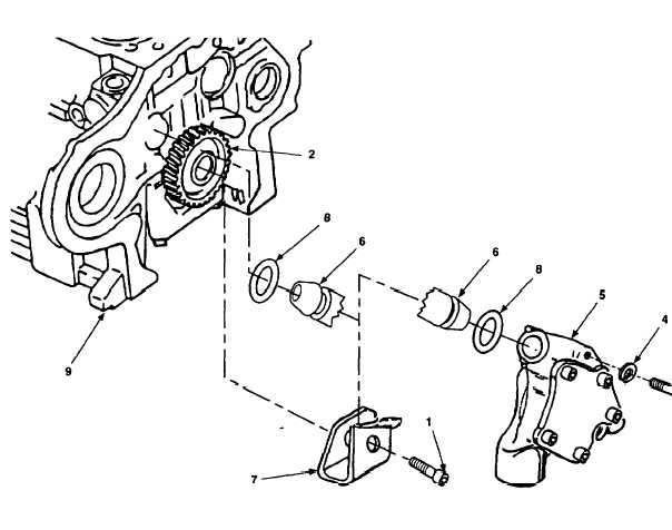
Figure 4-11.
0il Pump Assembly and Oil Pipe Replacement, Models
609-C and US636HCCD-1.
b.
Inspect all components and mounting hardware for damage.
c .
Replace all defective components.
4.4.7.4 Assembly.
a .
Position two new gaskets (8) and mounting bracket (7) on oil pipe (6).
b .
Install oil pipe (6) in oil pump assembly (5).
4.4.7.5 Assembly.
a .
Position oil pump assembly (5) against crankcase (9), with oil pipe assembly
(6) installed in crankcase (9), and secure with two new lock washers (4) and
screws (3).
Torque screws to 26 ft-lbs (35 N•m).
b .
Install screw (1) securing mounting bracket (7) to idler gear (2).
Torque
screw to 22 ft-lbs (30 N•m) .
c .
Using angle-of-turn indicator tighten screw (1) 60°.
4-27

