Google+
Facebook
LinkedIn
Twitter
Digg
StumbleUpon
Home
Download PDF
Order CD-ROM
Order in Print
BLEEDING AIR FROM FUEL SYSTEM - TM-5-4320-300-14_334
DISASSEMBLY - TM-5-4320-300-14_336
TM-5-4320-300-14 Pump Centrifugal Self-Priming Gasoline Engine Driven; 6-Inch 1500 GPM Capacity At 60 Foot Head Manual
Page Navigation
323
324
325
326
327
328
329
330
331
332
333
TM 5-4320-300-14
5-13.
FUEL CONTROL
TUBE ASSEMBLY
This task covers:
a.
Removal
b.
Disassembly
c.
Inspection
d.
Repair
e.
Assembly
f.
Installation
g.
Adjustment
INITIAL SETUP
Tools
General Safety Instructions
Shop set, automotive repair,
field maintenance, basic
NSN
4910-00-754-0705
WARNING
Tool kit, master mechanics
NSN
5180-00-699-5273
Severe burns, illness, or death may result
if personnel fail to handle diesel fuel
Materials/Parts
properly.. Observe the
following pre-
Diesel fuel oil (Item 6, Appendix E)
cautions:
·
Do not
inhale vapor.
Equipment Condition
Do not handle near open flame, sparks,
Engine side panels removed.
or excessive heat.
Be certain fuel
lines and connections are
Special
Environmental Conditions
secure.
Well-ventilated area required.
Work in a well-ventilated area
.
Location/Item
Action
Remarks
REMOVAL
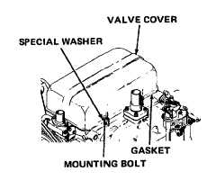
1. Valve cover and
gasket
Wipe off valve cover.
Remove valve
cover
mounting bolts, valve cover, and gasket.
Discard gasket
5-39
Integrated Publishing, Inc. - A (SDVOSB) Service Disabled Veteran Owned Small Business