TM 5-4320-300-14
6-10. PISTONS AND CONNECTING RODS (CONT)
Location/Item
Action
Remarks
35. Piston rings
If gap on new compression ring is insufficient, it
may be increased by filing or stoning the ends
of the ring. File or stone both ends of ring so
cutting action is from outer surface to inner sur-
face. This will prevent any chipping or peeling of
chrome plate on ring. The ends of the ring must
remain square and chamfer on outer edge must
be approximately 0.015 inch (0.381 mm). Re-
place a new oil control ring which fails to meet
ring gap tolerance. If piston ring side clearance
exceeds the limit, replace piston.
REASSEMBLY
36. Piston pin
If bushings were removed during overhaul,
bushings
install new bushings.
(in piston)
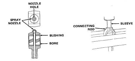
37. Connecting
Start replacement spray nozzle into connecting
rod spray
rod counterbore with the holes in a diamond
nozzle
pattern sideways to the bushing bore. Support
connecting rod in an arbor press. Place a short
3/8 inch (9.53 mm) inner diameter sleeve on
top of nozzle. Press nozzle into counterbore
until it bottoms.
38. Connecting
Clamp upper end of connecting rod assembly.
rod bushings
Start a replacement bushing straight into bore of
connecting rod, with bushing joint at top of rod.
Drive bushing in connecting rod. Turn rod over
and install second bushing in the same way.
NOTE
Bushings must be able to stand an end load of 2000 pounds (907 kg). If
bushing slides in easy, it probable will not stand the required end load.
Replace bushings or connecting rod if necessary.
6-87


