TM 5-4320-300-14
6-10. PISTONS AND CONNECTING RODS (CONT)
Location/Item
Action
Remarks
21. Piston-to-
Hold piston upside down in
liner clear-
cylinder liner (liner in block).
ance
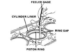
When performing piston-to-
liner clearance inspection, use
a feeler gage that is perfectly
flat and free of all nicks and
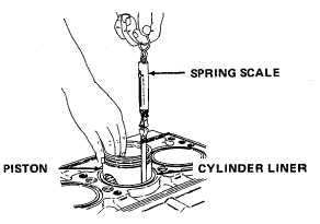
bends. Use a spring scale to
select a feeler gage with a
thickness which will require
a pull of 6 pounds (2.7 kg)
to remove. The clearance
will be 0.001 inch (0.0254
mm) greater than the thick-
ness of the feeler gage used.
If binding occurs, inspect piston and liner for
burrs. Remove burrs with a fine hone and re-
check clearance. Piston-to-liner clearance (with
new piston and liner) should be 0.0031 to
0.0068 inch (0.0787 to 0.1727 mm). A maxi-
mum clearance of 0.010 inch (0.254 mm) is
allowable with used parts.
NOTE
Each piston is fitted with a fire ring, three compression rings, and two oil
control rings. The top compression (fire) ring can be identified by the
bright chrome on the bottom side and oxide (rust color) on the top. The
second compression ring can be identified by its cast iron construction.
A two-piece oil control ring is used in both oil ring grooves. All new piston
rings must be installed whenever a piston is removed, regardless of whether
a new or used piston or cylinder liner is installed.
22. Piston ring
Use piston to push new rings, one at a time,
Push ring in far
gap
down into the cylinder liner. With a feeler
enough to be in the
gage, measure ring gap according to the
normal area of ring
following chart.
travel.
6-84