
TM 5-3825-270-23&P
0213
REMOVAL - Continued
3.
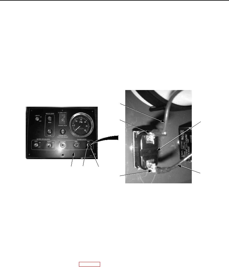
Remove nut (Figure 1, Item 2) and engine speed set button (Figure 1, Item 1) from cab control box cover
(Figure 1, Item 3).
END OF TASK
INSTALLATION
NOTE
Install engine speed set button as noted prior to removal.
1.
Install engine speed set button (Figure 2, Item 1) on cab control box cover (Figure 2, Item 3) with nut (Figure
2, Item 2).
5
4
1
3
2
1
6
7
Figure 2. Cab Control Box Engine Speed Set Button Installation.
NOTE
Install wires as noted prior to removal.
2.
Install black wire No. 1 (Figure 2, Item 6) on engine speed set button (Figure 2, Item 1) with screw (Figure 2,
Item 7).
3.
Install red wire (Figure 2, Item 5) on engine speed set button (Figure 2, Item 1) with screw (Figure 2, Item 4).
END OF TASK
FOLLOW-ON MAINTENANCE
Install cab control box faceguard. (WP 0205)
END OF TASK
END OF WORK PACKAGE