
TM 5-3825-270-23&P
0214
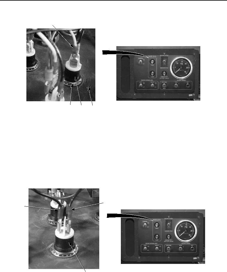
INSTALLATION - Continued
7
4, 5
3
6
Figure 3. Cab Control Box Water Level Indicator Installation.
NOTE
Install wires as noted prior to removal.
Perform Step (2) if installing low water level indicator.
2.
Install white wire No. 7 (Figure 3, Item 7) on water level indicator (Figure 3, Item 3).
NOTE
Perform Step (3) if installing high water level indicator.
3.
Install black wire (Figure 4, Item 2) on water level indicator (Figure 4, Item 3).
2
1
3
Figure 4. Cab Control Box Water Level Indicator Installation.