
TM 5-3825-270-23&P
FIELD MAINTENANCE
CAB CONTROL BOX ENGINE SPEED RPM SWITCH REPLACEMENT
INITIAL SETUP:
Tools and Special Tools
References
Tool Kit, General Mechanic's: Automotive
Parts Manual (WP 0220) Figure 4008
(WP 0225, Table 1, Item 12)
Equipment Condition
Materials/Parts
Cab control box faceguard removed. (WP 0205)
Tags, Identification, White (WP 0224, Table 1, Item
54)
REMOVAL
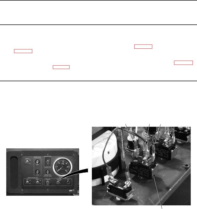
NOTE
Tag and mark wires prior to removal to ensure proper installation.
1.
Remove white wire No. 3 (Figure 1, Item 1) from engine speed RPM switch (Figure 1, Item 4).
1
2
3
4
Figure 1. Cab Control Box Engine Speed RPM Switch Removal.
2.
Remove two red wires (Figure 1, Item 2) from engine speed RPM switch (Figure 1, Item 4).
3.
Remove black wire (Figure 1, Item 3) from engine speed RPM switch (Figure 1, Item 4).
4.
Remove nut (Figure 2, Item 5) and engine speed RPM switch (Figure 2, Item 4) from cab control box cover
(Figure 2, Item 6).