
TM 5-3825-270-23&P
0207
REMOVAL - Continued
9, 10
9, 10
6
3
7
8
6
12, 13
11
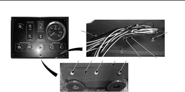
Figure 2. Cab Control Mounting Plate Removal.
NOTE
Tag and mark wires prior to removal to ensure proper installation.
3.
Remove nut (Figure 2, Item 12), two lockwashers (Figure 2, Item 13), two black wires (Figure 2, Item 11), screw
(Figure 2, Item 7), and cab control box mounting plate (Figure 2, Item 3) from cab control box (Figure 2, Item
8).
END OF TASK
INSTALLATION
NOTE
Install wires as noted prior to removal.
1.
Install cab control box mounting plate (Figure 3, Item 3) on cab control box (Figure 3, Item 8) with screw (Figure
3, Item 7), two black wires (Figure 3, Item 11), two lockwashers (Figure 3, Item 13), and nut (Figure 3, Item
12).