
TM 5-3825-270-23&P
0206
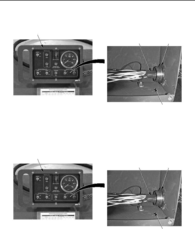
REMOVAL - Continued
2.
Remove retaining nut (Figure 2, Item 7) and wiring harness (Figure 2, Item 6) from cab control box (Figure 2,
Item 1).
1
6
7
1
Figure 2. Cab Control Box Wiring Harness Removal.
END OF TASK
INSTALLATION
1.
Install wiring harness (Figure 3, Item 6) in cab control box (Figure 3, Item 1) with retaining nut (Figure 3, Item
7).
1
6
7
1
Figure 3. Cab Control Box Wiring Harness Installation.
2.
Install two black wires (Figure 4, Item 2) on cab control box (Figure 4, Item 1) with screw (Figure 4, Item 5) two
lockwashers (Figure 4, Item 4) and nut (Figure 4, Item 3).