
TM 5-3825-270-23&P
FIELD MAINTENANCE
DIAL INDICATOR ADJUSTMENT
INITIAL SETUP:
Tools and Special Tools
Equipment Condition
Tool Kit, General Mechanic's: Automotive
Water Distributor on Level Surface. (TM
(WP 0225, Table 1, Item 12)
5-3825-270-10)
ADJUSTMENT
CAUTION
Water distributor must be on level ground to get an accurate reading. Failure to comply may
result in false readings and damage to equipment may occur.
1.
Open manhole cover. (TM 5-3825-270-10)
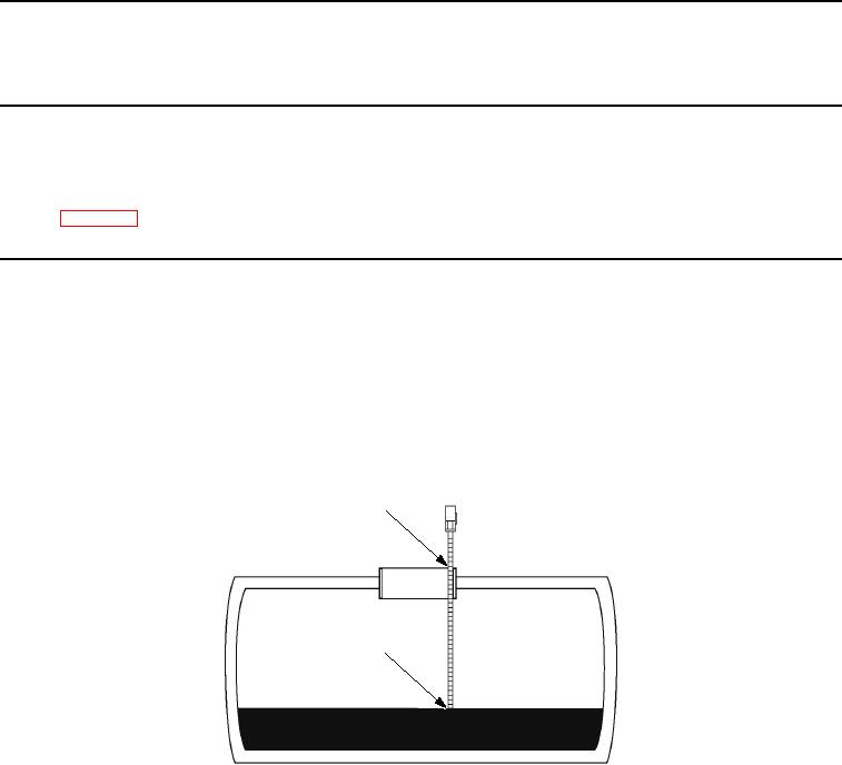
2.
Using a tape measurer, measure from top of water surface to top edge of manhole. Record measurement.
Read Number at top edge
of manhole, then refer
to chart to determine
water volume in tank.
End of tape touches
top of water.
Figure 1. Dial Indicator Adjustment.
3.
Loosen hex head screw (Figure 2, Item 2) and locknut (Figure 2, Item 3).