
TM 5-3825-270-23&P
FIELD MAINTENANCE
STRAINER HOUSING REPLACEMENT
INITIAL SETUP:
Personnel Required
Tools and Special Tools
Construction Equipment Repairer 91L (2)
Tool Kit, General Mechanic's: Automotive
(WP 0225, Table 1, Item 12)
Wrench, Torque, 40-200 lb-in (6-23 Nm), 3/8 in.
References
Drive (WP 0225, Table 1, Item 14)
Parts Manual (WP 0220) Figure 4007
Materials/Parts
Equipment Condition
Locknut (WP 0226, Table 1, Item 64) Qty: 20
Water tank completely drained. (TM 5-3825
Gasket (WP 0226, Table 1, Item 34) Qty: 2
270-10)
Gasket (WP 0226, Table 1, Item 34) Qty: 1
REMOVAL
1.
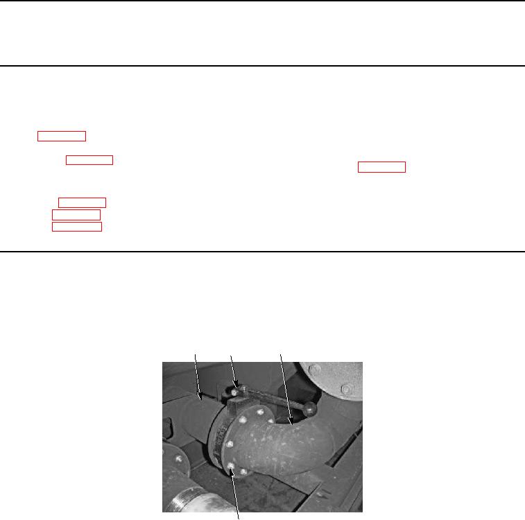
Remove eight locknuts (Figure 1, Item 5), screws (Figure 1, Item 6), two gaskets (Figure 1, Item 2), and valve
V1 (Figure 1, Item 3) from water tank assembly (Figure 1, Item 1) and strainer housing (Figure 1, Item 4).
Discard locknuts and gaskets.
1
2, 3
4
5, 6
Figure 1. Strainer Housing Removal.
2.
Remove eight locknuts (Figure 2, Item 8), cap (Figure 2, Item 11), hose adapter (Figure 2, Item 10), gasket
(Figure 2, Item 9), and screws (Figure 2, Item 7) from strainer housing (Figure 2, Item 4). Discard locknuts and
gasket.