
TM 5-3825-270-23&P
0154
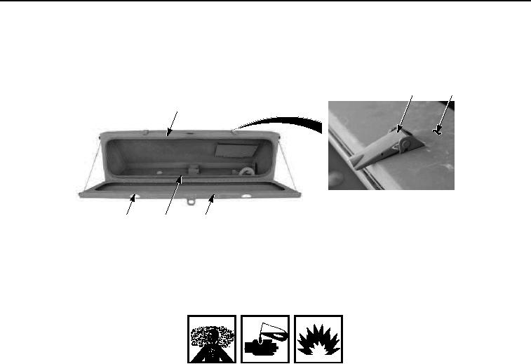
ASSEMBLY - Continued
5.
Using four rivets (Figure 7, Item 6), install two latches (Figure 7, Item 7) on stowage box door (Figure 7, Item
4).
2, 3
1
1
6, 7
5
4
Figure 7. Stowage Box Assembly.
6.
Using four screws (Figure 7, Item 3), install two draw latches (Figure 7, Item 2) on stowage box (Figure 7, Item
1).
WARNING
Adhesives, solvents, and sealing compounds can burn easily, can give off harmful vapors,
and are harmful to skin and clothing. Keep away from open fire and use in well-ventilated
area. If adhesive, solvent, or sealing compound gets on skin or clothing, wash immediately
with soap and water. Failure to comply may result in injury or death to personnel.
NOTE
Install stowage box door seal so that seam of seal is on bottom side of stowage box assembly.
7.
Apply adhesive compound to mounting edges of stowage box door seal (Figure 7, Item 5).
8.
Starting at bottom center, install stowage box door seal (Figure 7, Item 5) on stowage box (Figure 7, Item 1).
END OF TASK
INSTALLATION
1.
Install stowage box (Figure 8, Item 1) on flat rack (Figure 8, Item 3) with six screws (Figure 8, Item 7), twelve
washers (Figure 8, Item 6), and nuts (Figure 8, Item 5).