
TM 5-3825-270-23&P
0135
INSTALLATION - Continued
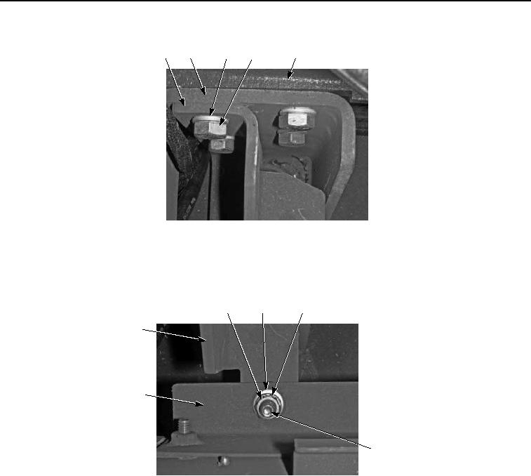
8
5
15
16
17
Figure 13. Rear Engine Mounting Bracket and Bushing Installation.
6.
Install engine compartment side rail (Figure 14, Item 14) on support bracket (Figure 14, Item 8) with washer
(Figure 14, Item 13), screw (Figure 14, Item 12), washer (Figure 14, Item 10), lockwasher (Figure 14, Item 11),
and nut (Figure 14, Item 9).
9
10
11
8
14
12, 13
Figure 14. Rear Engine Mounting Bracket and Bushing Installation.
7.
Secure engine mount bracket (Figure 15, Item 5) on frame (Figure 15, Item 7) with upper isolator mount (Figure
15, Item 6), upper snubbing washer (Figure 15, Item 1), washer (Figure 15, Item 4), screw (Figure 15, Item 3),
and locknut (Figure 15, Item 2). Tighten locknut to 150 lb-ft (203 Nm).