
TM 5-3825-270-23&P
0119
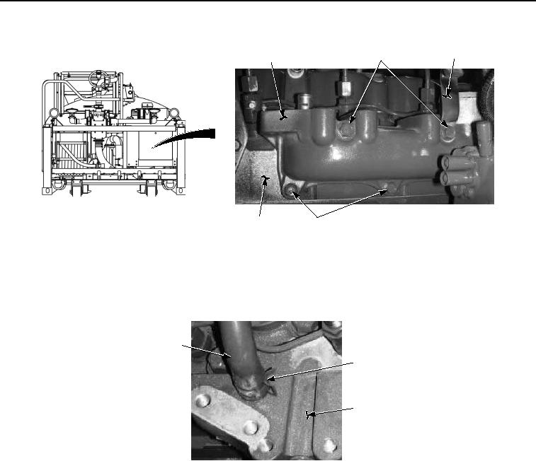
INSTALLATION - Continued
11
10
8, 9
12
13
Figure 4. Inlet Assembly Manifold Installation.
2.
Install bracket (Figure 4, Item 11) and three screws (Figure 4, Item 10) on inlet assembly manifold (Figure 4,
Item 8).
3.
Install vent hose (Figure 5, Item 6) on inlet assembly manifold (Figure 5, Item 8) with clamp (Figure 5, Item 7).
6
7
8
Figure 5. Inlet Assembly Manifold Installation.
4.
Install bracket (Figure 6, Item 3) on injection pump assembly (Figure 6, Item 5) and engine block (Figure 6,
Item 1) with two nuts (Figure 6, Item 4) and screws (Figure 6, Item 2).