
TM 5-3825-270-23&P
0119
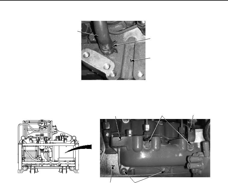
REMOVAL - Continued
6
7
8
Figure 2. Inlet Assembly Manifold Removal.
3.
Remove three screws (Figure 3, Item 10) and bracket (Figure 3, Item 11) from inlet assembly manifold (Figure
3, Item 8).
11
10
8, 9
12
13
Figure 3. Inlet Assembly Manifold Removal.
4.
Remove five screws (Figure 3, Item 12), inlet assembly manifold (Figure 3, Item 8), and gasket (Figure 3, Item
9) from cylinder head (Figure 3, Item 13). Discard gasket.
END OF TASK
INSTALLATION
1.
Install gasket (Figure 4, Item 9) and inlet assembly manifold (Figure 4, Item 8) on cylinder head (Figure 4, Item
13) with five screws (Figure 4, Item 12).