
TM 5-3825-270-23&P
0060
DECISION
No - Go to step 7. (Step 7 - Are less than 200 ohms measured at UPIK harness connector pin B to known good
ground?)
Yes - Go to step 5. (Step 5 - Are less than 200 ohms measured on white wire at cab control box engine speed
RESUME/IDLE switch to known good ground?)
STEP 5
Are less than 200 ohms measured on white wire at cab control box engine speed RESUME/IDLE switch to
known good ground?
1.
Ensure multimeter is set to measure continuity.
WARNING
Ensure electrical power is off prior to working on all electrical systems. Failure to comply
may result in injury or death to personnel.
Remove all jewelry, such as rings, ID tags, bracelets, etc., prior to working on or around
equipment. Jewelry and tools can catch on equipment, contact positive electrical circuits,
and cause a direct short, severe burns, or electrical shock. Failure to comply may result
in injury or death to personnel.
2.
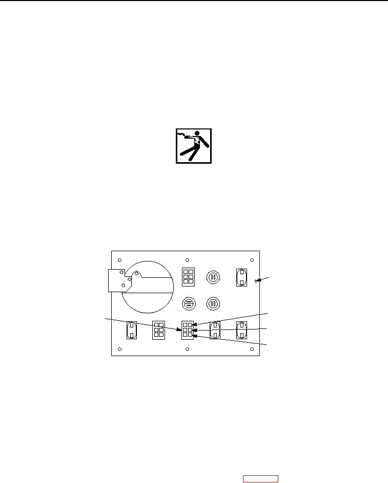
Connect red multimeter lead to white wire at cab control box engine speed RESUME/IDLE switch.
BACK OF CAB
CONTROL BOX
CAB
WHITE WIRE
CONTROL BOX
ENGINE SPEED
RED JUMPER WIRES
RESUME/IDLE
SWITCH
BLACK WIRE
Figure 6. Cab Control Box Engine Speed Resume/Idle Switch - Step 5.
3.
Connect black multimeter lead to known good ground.
4.
Note multimeter reading.
CONDITION/INDICATION
Are less than 200 ohms measured on white wire at cab control box engine speed RESUME/IDLE switch to
known good ground?
DECISION
No - Go to step 6. (Step 6 - Are less than 200 ohms measured at UPIK harness connector pin C to known good
ground?)
Yes - Replace cab control box engine speed RESUME/IDLE switch. (WP 0211) Verify problem is solved. (Step
8 - Does cab control box engine speed RESUME/IDLE switch operate?)
STEP 6