
TM 5-3825-270-23&P
0031
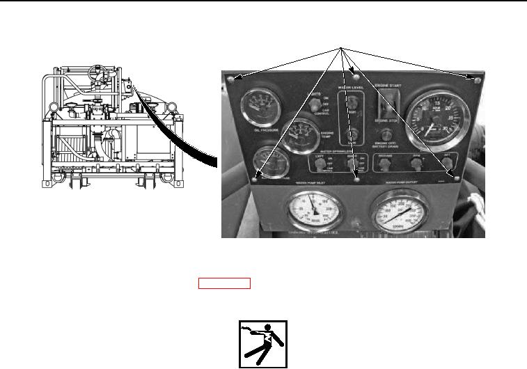
CONTROL PANEL
FACEPLATE SCREWS
Figure 1. Control Panel Faceplate Screws - Step 2.
4.
Set multimeter to measure continuity. (WP 0004)
WARNING
Ensure electrical power is off prior to working on all electrical systems. Failure to comply
may result in injury or death to personnel.
Remove all jewelry, such as rings, ID tags, bracelets, etc., prior to working on or around
equipment. Jewelry and tools can catch on equipment, contact positive electrical circuits,
and cause a direct short, severe burns, or electrical shock. Failure to comply may result
in injury or death to personnel.
5.
Connect red multimeter lead to positive terminal strip, terminal 15.