
TM 5-3825-270-10
0006
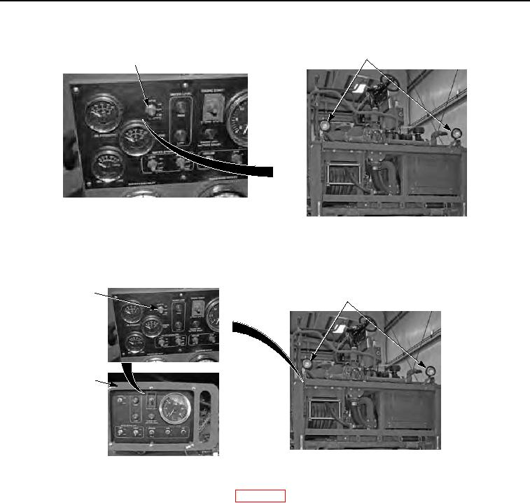
OPERATING LIGHTS - Continued
4
3
Figure 2. Operating Lights.
4.
Place light switch (Figure 3, Item 3) to CAB CONTROL to operate work lights (Figure 3, Item 4) from cab control
box (Figure 3, Item 5).
3
4
5
Figure 3. Operating Lights.
5.
Connect universal power interface kit (UPIK) (WP 0012).
NOTE
Ensure emergency stop switch is in the OFF position when mission is complete.
6.
Place light switch (Figure 4, Item 3) on cab control box (Figure 4, Item 5) to ON position to turn work lights
(Figure 4, Item 4) on, and back to OFF to turn work lights off.