
TM 5-3825-270-10
0004
Table 1. MAIN CONTROL PANEL - Continued
Control/Indicator
Function
Key
13
Set Button
Pressed in to set desired RPM during operation.
14
15
16
17
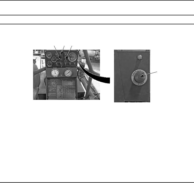
Figure 3. Control Panel.
14
Water Level Low
Illuminates steady when tank capacity is approximately 300 gallons or lower.
Indicator
15
Water Level High
Illuminates when tank capacity is approximately 3000 gallons.
Indicator
16
Engine Off/ Battery
Illuminates when emergency shutoff switch has been released, indicates that
Drain Indicator
power is still in use and that battery is being drained.
Emergency Stop
Allows the operator to immediately shut down the system in an emergency
17
Switch
situation.