
TM 5-3825-270-10
0004
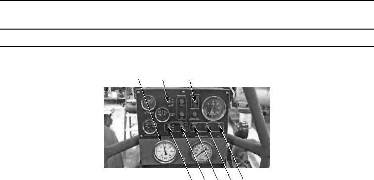
Table 1. MAIN CONTROL PANEL - Continued
Control/Indicator
Function
Key
6
7
8
9
10 11 12 13
Figure 2. Control Panel.
6
Water Pump Inlet
Displays water input in pounds per square inch (psi) and vacuum in (Hg).
Gauge
7
Light Switch
Used to turn work lights on or off.
8
Engine ON/OFF
Used to start and stop engine.
Switch
9
Left Side Water
Used to turn Left Sprinklers on, off, and relay control to cab control box.
Sprinkler Switch
10
Right Side Water
Used to turn Right Sprinklers on, off, and relay control to cab control box.
Sprinkler Switch
11
Resume/Idle Switch
Used to run engine at idle speed or to resume set RPM for operation.
12
RPM Switch
Used to raise or lower desired RPM for operation.