
TM 5-3820-276-10-2
0206
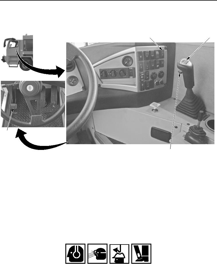
WWDR REAR WHEEL AND TIRE ASSEMBLY REPLACEMENT - Continued
47.
Depress clutch pedal (Figure 13, Item 4).
1
2
4
3
WWDS00603
Figure 13. WWDR Gearshift Lever.
48.
Place transmission gearshift lever (Figure 13, Item 2) in Neutral position.
49.
Set high-lo range control handle (Figure 13, Item 3) to down (low) position.
50.
Set RIG MODE/ROAD MODE switch (Figure 13, Item 1) to ROAD MODE position.
51.
Release clutch pedal (Figure 13, Item 4).
52.
Shut down WWDR (Volume 1, WP 0012).
END OF TASK
WWDR FRONT WHEEL AND TIRE ASSEMBLY REPLACEMENT
WARNING
Always wear double hearing protection, safety glasses, hard hat, gloves, and steel toe
shoes during operation of the Water Well Drilling System. Failure to comply may result in
injury or death to personnel. Seek medical attention in the event of an injury.
02/13/2013root(maintwp)wpno(M00009)