
TM 5-3820-276-10-1
0032
CAB SETUP PROCEDURES - Continued
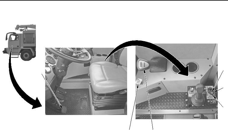
2
1
3
4
6
5
WWDS00256
Figure 2.
Cab Setup.
3.
Depress clutch pedal (Figure 2, Item 1).
4.
Put gearshift lever (Figure 2, Item 5) into Neutral.
NOTE
Wait 1 minute for Power Take-Off (P.T.O.) gears to stop turning.
5.
Push button (Figure 2, Item 2) and move P.T.O. lever (Figure 2, Item 3) to IN position.
6.
Ensure P.T.O. engaged light (Figure 2, Item 4) is on. Light will illuminate when P.T.O. is engaged.
7.
Release clutch (Figure 2, Item 1).
END OF TASK