• Home
  • Download PDF
  • Order CD-ROM
  • Order in Print
Figure 13. Drill Rods Detached.
Figure 15. Tophead Mounted Wrench Foot Switch.

Technical Manual For Water Well Drilling System (Wwds) - 1 Page Navigation
  284    285    286    287    288  289  290    291    292    293    294  
img
.
TM 5-3820-276-10-1
0025
ARHS STORING OF DRILL ROD OPERATION - Continued
2
1
3
4
5
6
7
WWDS01047
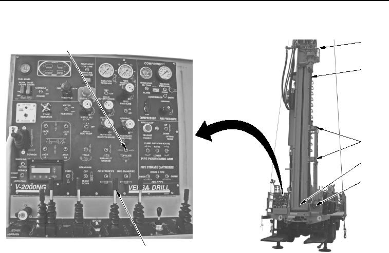
Figure 14. Tophead Slide Switch.
10.
Push FAST FEED control (Figure 14, Item 7) forward to raise upper drill rod (Figure 14, Item 3) up until
threads (Figure 14, Item 5) are approximately 1 in. (25 mm) above base of automated rod handling arm
(Figure 14, Item 6).
0025-15
02/13/2013root(opusualwp)wpno(O10009)


Privacy Statement
Press Release
Contact

© Copyright Integrated Publishing, Inc.. All Rights Reserved.