TM 10-4630-207-13&P
0037 00
2. To make more substantial adjustments, proceed as follows:
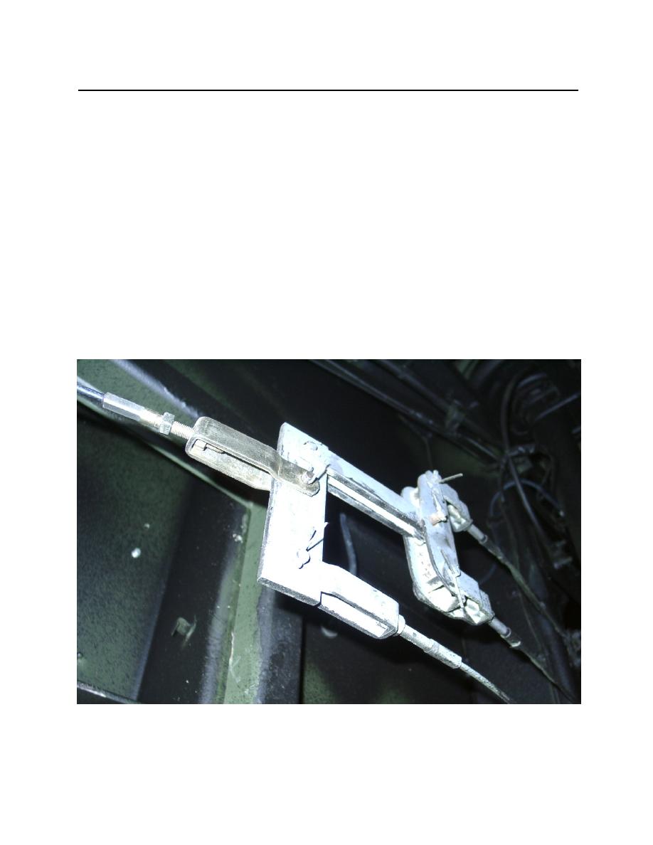
a. Locate threaded end of brake cable (figure 2, item 1) and cable clamp (figure 2, item 2).
b. Remove the cotter pin (figure 2, item 3) holding the retaining pin (figure 2, item 4) and cable
clamp (figure 2, item 2) to the spreader bar (figure 2, item 5).
c.
Remove the cable clamp (figure 2, item 2) from the spreader bar (figure 2, item 5). Turn the
adjusting nut (figure 2, item 6) to the right to tighten the brakes or to the left to loosen the brakes.
d. Secure the cable (figure 2, item 1) to the cable clamp (figure 2, item 2) by tightening the
adjusting nut (figure 2, item 6) and brake cable lock nut (figure 2, item 7).
e. Connect the cable clamp (figure 2, item 2) to the spreader bar (figure 2, item 5) with the
retaining pin (figure 2, item 4).
f.
Fasten retaining pin (figure 2, item 4) in place with cotter pin (figure 2, item 3).
g. Perform adjustment procedures within this work package to check adjustment of brakes.
Figure 2. Collective Brake Adjustment
0037 00-2


