
TM 10-4630-207-13&P
0027 00
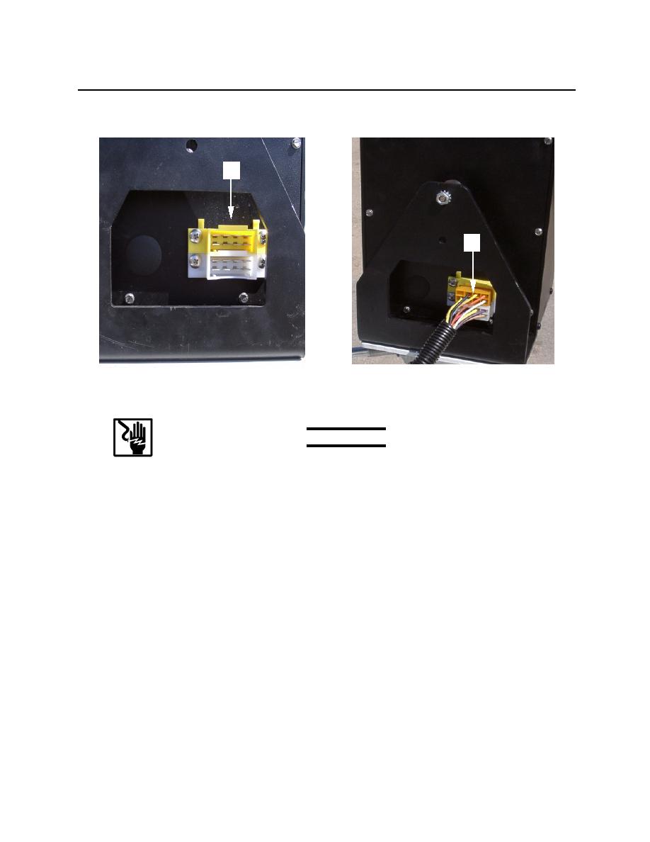
23. Locate the 8-pin yellow and white male connectors (figure 9, item 1) at the rear of the control box and
connect the orange and white external wire harness (figure 9, item 2) to it.
1
2
Figure 9. Control Panel External Harness Connection
TEST
WARNING
To prevent injuries from electrical shock ensure battery cable is disconnected
at the negative terminal post before making any repairs to the control box.
NOTE
The gages and controls on the control panel can be tested to check electrical continuity.
Refer to the wiring diagram in Figure 10.
1. To test the instruments, proceed as follows: Remove the wires from the instrument to be tested as
described under REPLACE in this WP.
2. Attach the leads of a multimeter to the positive (+) and negative (-) contacts on the back of the
voltmeter, the oil pressure gage, the water temperature gage, the tachometer, or the key switch as
applicable.
3. If no continuity is present, indicating an open circuit, replace the instrument as described under
REPLACE in this WP.
4. Failure of multiple instruments or the emergency button and key switch is indicative of a printed circuit
board failure. Replace the entire box. Remove it as described in paragraphs 1., and 2., and install it as
described in paragraphs 21., and 22., under REPAIR in this WP.
0027 00-7
