
TM 10-4630-207-13&P
0027 00
4. Separate control panel (figure 4, item 1) from bracket (figure 4, item 2). Recover washers (figure 4,
item 3) on isolation mounts (figure 4, item 4).
1
4
4
3
2
Figure 4. Removing Control Box from Bracket
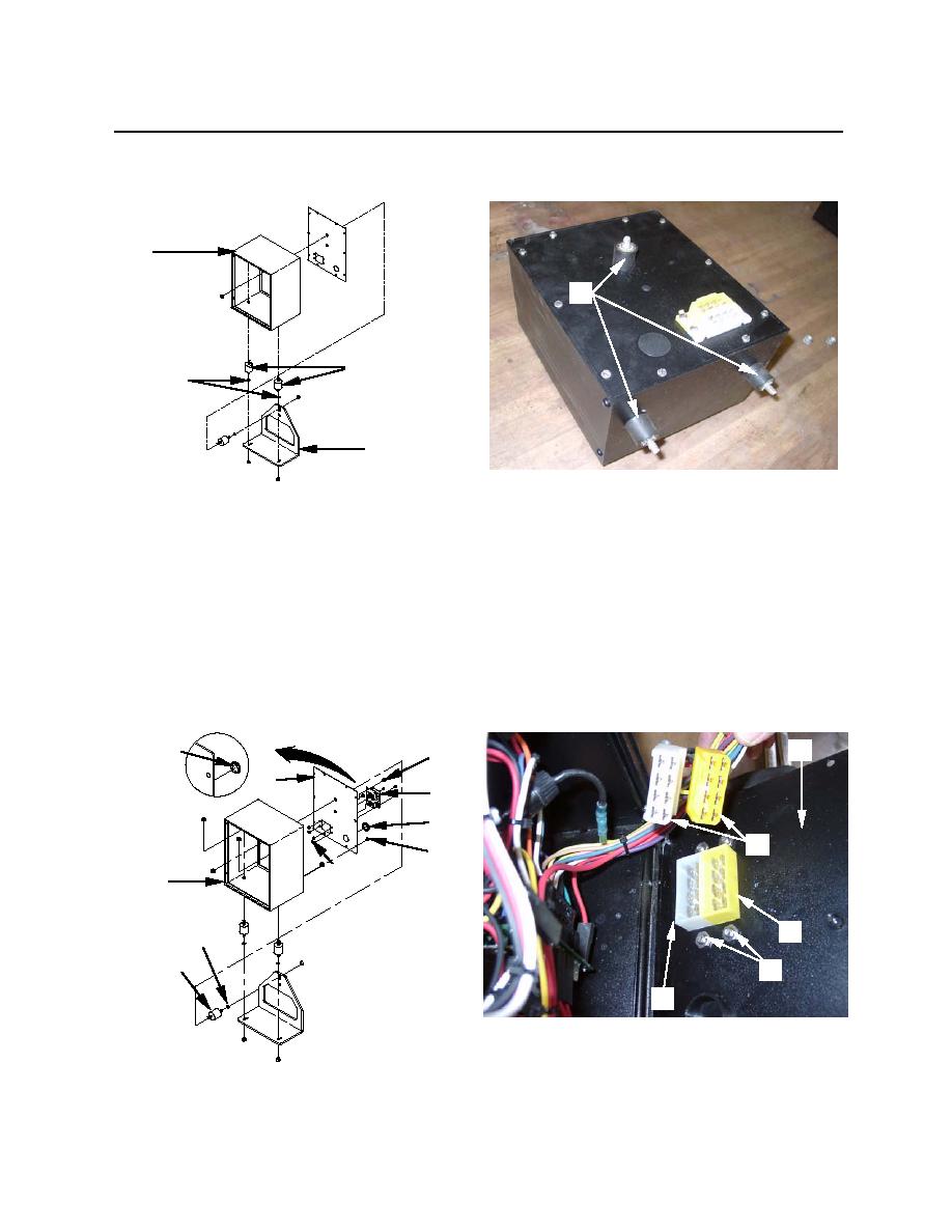
5. To remove the backpanel (figure 5, item 1), unscrew and remove ten slotted hex head screws (figure
5, item 2) that hold the panel to the enclosure (figure 5, item 3). Tilt the backpanel open and separate
the internal harness connectors (figure 5, item 4) from the 8-position male connectors (figure 5, item
5) mounted on the backpanel (figure 5, item 1).
6. Remove large (figure 5, item 6), and small (figure 5, item 7) dome plug. Remove rear isolation mount
(figure 5, item 8) and washer (figure 5, item 9).
7. Remove four cross-tipped screws (figure 5, item 10) holding the 8-position male connectors (figure 5,
item 5) to the backpanel (figure 5, item 1). Remove the connectors from the panel. Recover four nuts
(figure 5, item 11).
1
7
10
1
5
6
4
2
11
3
5
9
8
11
5
Figure 5. Removal of Backpanel
0027 00-3
