
TM 10-4630-207-13&P
0027 00
REPLACE
WARNING
To prevent injuries from electrical shock ensure battery cable is disconnected
at the negative terminal post before making any repairs to the control box.
NOTE
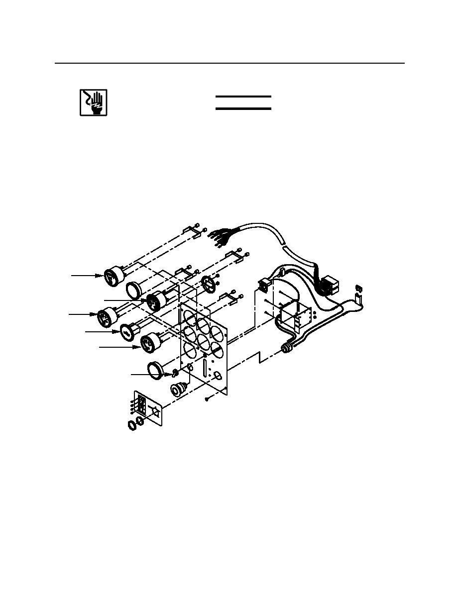
Replace a voltmeter (figure 11, item 1), oil pressure gage (figure 11, item 2), water
temperature gage (figure 11, item 3), tachometer (figure 11, item 4), hour meter (figure
11, item 5), or toggle switch (figure 11, item 6) as follows:
1
4
2
5
3
6
Figure 11. Front Panel Assembly
1. Disassemble the control panel as described in step 1., through step 9., under REPAIR in this WP.
2. Tag and disconnect wires (figure 12, item 1) from the instrument (figure 12, item 2) to be replaced.
3. Remove hex nuts (figure 12, item 3) from mounting brackets (figure 12, item 4) on the voltmeter
(figure 12, item 5), oil pressure gage (figure 12, item 6), and temperature gage (figure 12, item 7)
0027 00-9
