TM 10-4320-344-24
3.8.15 Oil Nozzle Replacement, Model US636HCCD-1.
This task covers:
3.8.15.1
Removal
3 .
8 .1 5 . 2 I n s t a l l a t i on
INITIAL SETUP
Material/Parts
Tools
Screw, 0.25 inch diameter by 1.50 inches
General Mechanic’s Automotive
long
Tool Kit, Appendix B, Section
III, Item 1
Equipment Conditions
Drill, Mechanical, Appendix B,
Pumping station shut down, TM 10-4320-
Section III, Item 2
344-10.
Drill Set, Twist, Appendix B,
Oil Cooler removed, paragraph 2.21.30.
Section III, Item 2
General Safety Instructions
Puller Kit, Mechanical, Appendix B,
Section III, Item 2
Do not work on equipment that is not
securely stabilized to prevent rolling
Threading Set, Screw, Appendix B,
o r s l i d i n g.
Section III, Item 3
Do not work on equipment without follow-
Nozzle Tool, Appendix B, Section III,
Item 16
ing standard shop safety practices.
3.8.15.1 Removal.
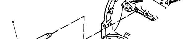
Figure 3-33.
Oil Nozzle Replacement, Model US636HCCD-1.
a .
Drill and tap 0.250 inch (6.35 mm) diameter hole in oil nozzle (Figure 3-33,
1), approximately 1.5 inches (38.1 mm) deep.
3-78