TM 10-4320-344-24
3.8.14 Oil Pump Assembly Maintenance. Model 609-A.
This task covers:
3.8.14.1 Removal
3 .
8 .1 4 . 2 I n s t a l l a t i on
INITIAL SETUP
Tools
Equipment Conditions
General Mechanic’s Automotive
Tachometer Shaft and Angle Drive removed,
Tool Kit, Appendix B, Section III,
paragraph 2.21.45.
Item 1
Oil pan removed, paragraph 3.8.12.
Torque Wrench, Appendix B, Section
III, Item 2
General Safety Instructions
Material/Parts
Do not work on equipment without follow-
ing standard shop safety practices.
Rags, Appendix C, Item 20
Lock Washers (TM 10-4320-344-24P)
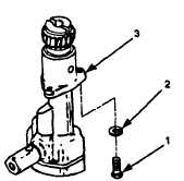
3.8.14.1 Removal.
Figure 3-32.
Oil Pump Assembly, Model 609-A.
a.
Turn crankshaft so no. 1, 4, or 6 piston is at TDC.
b.
Remove two bolts (Figure 3-31,
1) and lock washers (2) that secure flange of
oil pump assembly (3) to cylinder block.
Discard lock washers (2).
c .
Rotate crankshaft and, at the same time, remove oil pump assembly (3) with
spiral motion.
3.8.14.2 Installation.
a.
Turn engine crankshaft so no. 1, 4, or 6 piston is at TDC.
b .
Rotate crankshaft and, at the same time,
install oil pump assembly (3) with
spiral motion.
Ensure arrow on oil pump gear is aligned with arrow on fuel
pump attaching pad.
c .
Install two new lock washers (2) and bolts (1) securing oil pump assembly (3)
to cylinder block.
Torque bolts (1) to 25 ft-lbs (34 N•m).
3-77