TM 10-4320-344-24
NOTE
This testing procedure applies to Model 609-A.
The testing procedure for
Model US636HCCD-1 is identical.
To read alternator output voltage for Model
609-c read voltmeter on control panel.
a .
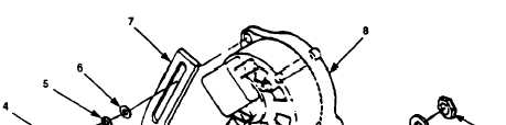
Connect multimeter to alternator ground terminal (Figure 2-130, 1) and
positive output terminal (2).
Set multimeter for voltage test.
To prevent electrical shock, use caution when testing voltage output.
b.
Refer to TM 10-4320-344-10 and start engine.
Run pumping assembly at about
1,000 rpm.
The voltage value to check for on Model US636HCCD-1 is 12 to 14.8 volts. The
voltage value to check for on Model 609-C is approximately 28 volts.
c .
If voltage is not between 13.8 and 14.8 volts, replace alternator (3).
d.
Refer to TM 10-4320-344-10 and stop engine.
The removal, inspection, and installation procedures apply to Model 609-A.
The removal, inspection, and installation procedures for Models 609-C and
US636HCCD-1 are similar.
2.21.16.2 Removal.
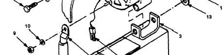
Figure 2-131. Alternator Replacement (Model 609-A Shown).
a.
Loosen nut (Figure 2-131, 1) and screw (2) on alternator mounting bracket (3).
2-299
NOTE
NOTE