TM 10-4320-344-24
(5)
(6)
(7)
(8)
(9)
e .
f .
g .
h.
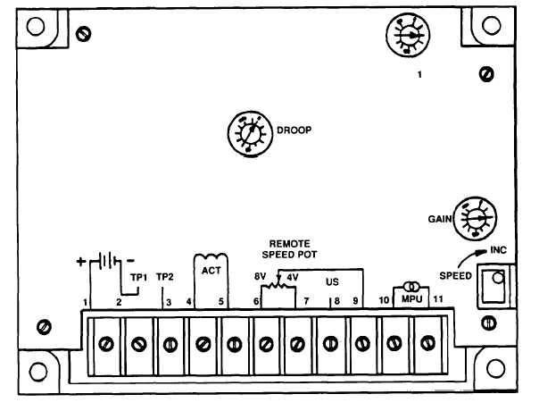
Figure 2-87. Governor Control Module Adjustment With Cover Removed.
If system is unstable (oscillates), slightly reduce the I and GAIN settings
u n t i l o s c i l l a t i o n s t o p s .
Turn AUTO THROTTLE rheostat (Figure 2-86, 8) to the IDLE position.
Slowly turn the GAIN adjustment clockwise (CW) until the governor actuator
lever begins to oscillate, then turn back until oscillation stops.
Upset the governor actuator lever by hand and note how many oscillations it
takes for the lever to again stabilize. If no more than 5 oscillations are
required, adjustment is correct.
If adjustment is not correct (3-5 oscillations in step 8 above) reduce GAIN
setting counter–clockwise (CCW) one division and while observing the
actuator lever turn the I adjustment CW until the governor actuator lever
o s c i l l a t e s.
If the governor actuator lever does not become unstable, upset it by hand.
When the governor actuator lever oscillates, slowly turn the I adjustment CCW
until the lever is stable.
Upset the governor actuator lever again, it should oscillate 3 to 5 times and
then become stable.
If unit cannot be adjusted, replace governor control module with another
governor control module.
2-215