TM 10-4320-344-24
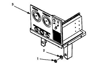
Figure 2-57.
Control Panel Assembly Removal and
i .
Remove four attaching nuts (Figure 2-57, 1),
panel assembly (3)
2.16.5.2 Installation.
a.
b.
c .
d .
e.
f .
g .
h.
i .
Installation, Model US636HCCD-1.
lock washers (2), and control
Position control panel assembly (3) on pumping assembly and secure with four
lock washers (2) and nuts (1).
Insert wiring harness (Figure 2-56, 10), hose assemblies (1, 3 and 5), engine
tachometer drive cable (7), and wires (13 and 16) through control panel
assembly mounting plate (19).
Holding terminal connector (18) push backward and connect wire (16) on
a l t e r n a t o r l i g h t ( 1 7 ).
Remove and discard tag.
Connect wire (13) to screw (15) at terminal 2 of controlling device (14).
Tighten screw (15) and remove and discard tag.
Connect ten wires (9) from wiring harness (10) to ten screws (12) on terminal
b l o c k ( 1 1 ).
Tighten screws (12) and remove and discard tags.
Install engine tachometer drive cable (7) on tachometer/hourmeter gauge (8).
Remove and discard tag.
Install engine oil pressure gauge hose (5) on oil pressure gauge (6).
Remove
and discard tag.
Install discharge elbow hose (3) on discharge gauge assembly (4).
Remove and
discard tag.
Install suction elbow hose (1) on suction gauge assembly (2).
Remove and
discard tag.
2-153