TM 10-4320-307-24
4-17
CRANKSHAFT ASSEMBLY REPLACE,REPAIR (CONT)
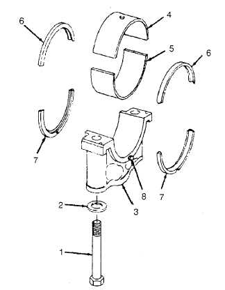
5.
Install hexagon screws (1) and washers (2) in
each bearing cap (3).
6.
Coat upper and lower main bearing shells (4
and 5) with lubricating oil.
NOTE
The upper main bearing shells have a
groove and an oil hole to provide
crankshaft lubrication. The lower main
bearing shells do not. The groove for the
No. 7 shell is not in the center of the shell.
The wider part of the No. 7 shell must be
installed toward the flywheel end of the
cylinder block.
7.
Install upper main bearing shells (4) into bearing
brackets
of
crankcase,
In
accordance
with
markings made during removal. If new shells are
used, be sure that correct part number shells are
used at each location.
8.
Install lower main bearing shells (5) into bearing
caps (3), in accordance with markings made dur-
ing removal.
CAUTION
Grooves in thrust rings must be toward the crankshaft.
9.
Coat thrust rings (6 and 7) with clean lubriplate 105, or equivalent, and install upper thrust rings (6) in No. 7 main
bearing saddle in crankcase. Refer to location markings on rings made during disassembly.
10. Install lower thrust rings (7) in No. 7 main bearing cap as shown, in accordance with markings made on rings during
removal. Be sure that locating dowels (8) in bearing cap fit into dowel holes in rings.
11. Lubricate threads of hexagon screws (1) and washers (2) with lubricating oil and drain excess oil before installing.
4-133