TM 5-4320-300-14
6-4. BLOWER ASSEMBLY
This task covers:
a.
Disassembly
b.
Cleaning
c.
Inspection/Repair
d.
Assembly
INITIAL SETUP
Tools
Plain washers, 3/8 inch (2)
Emery abrasive cloth (Item 2, Appendix E)
Shop set, automotive repair,
field maintenance, basic
Lubricating oil (Item 10, Appendix E)
NSN 4910-00-754-0705
Nuts, 3/8-16 inch (4)
Tool kit, master mechanics
Troubleshooting References
NSN 5180-00-699-5273
Malfunction 3, step 1
Materials/Parts
Malfunction 4, step 1
Rear plate-to-engine end plate gasket
Equipment
Condition
Cover plate gasket
Para
Condition Description
Blower-to-block gasket
5-9
Blower assembly removed from engine.
Oil seals
Special Environmental Conditions
Plain washers, 5/16 inch (2)
Well-ventilated area required during cleaning.
Location/Item
Action
Remarks
DISASSEMBLY
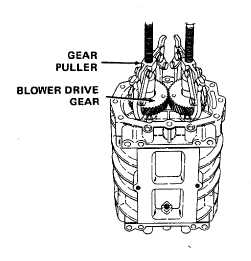
1. Blower drivegears
Wedge
a
clean
cloth between rotor
assemblies
to
prevent them from
turning. Remove
drive
gear
bolts
and
washers.
Mark
right-hand
helix
gear
(for
6-6