TM 5-4320-300-14
5-14.
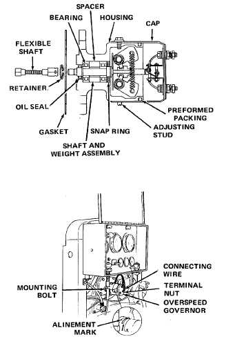
OVERSPEED GOVERNOR (CONT)
Location/Item
Action
Remarks
12. Shaft and weight
assembly shaft.
13. Governor cap
14. Flexible shaft and
retainer
INSTALLATION
15. Governor and
gasket
Slide
through
bearings;
install
snap ring on.
Position cap on housing, matching
the alinement marks made during
disassembly. Install and tighten
adjusting stud and screw.
Slip flexible shaft onto governor
shaft; secure with retainer.
Hold
governor
and
gasket
in
position, and slide socket end of
flexible shaft over end of cam-
shaft. Install mounting bolts and
tighten
securely.
Install
connecting wires.
ADJUSTMENT
16. Adjusting
Loosen adjusting stud and screw and turn cap
stud and
clockwise or counterclockwise from the aline-
screw
ment mark until desired trip speed is reached.
Clockwise rotation of cap lowers the trip speed
and counterclockwise rotation increases the
trip speed. The total range of adjustment of
the governor is indicated on governor nameplate.
The governor should not be adjusted to trip be-
low 100 rpm above the normal running speed
of the governor. Make sure the adjusting stud
and screw are tightened after adjustment has
been completed.
5-49