
TM 5-4320-275-13 & P
ENGINE (CONT)
LOCATION/ITEM
ACTION
REMARKS
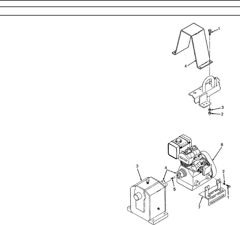
3. Coupling guard
Use 7/16 inch socket and handle to remove 4
cap screws (1) and lockwashers (3). Hold nuts
(2) with 7/16 inch wrench. Remove coupling
guard (4) by lifting straight up.
4.
Engine
Use 7/16 inch wrench to re-
move 12 cap screws (1) and
lockwashers (2) from engine
(6). Slide engine away from
gear reducer (3). Use a 5/32
inch hex key to loosen set-
screw in engine coupling (4)
half. Remove coupling half
from engine. Remove and
discard key (5). Lift engine
(6).off frame (7).
NOTE
It may be necessary to use a mechanical gear and bearing, puller to remove
coupling half from engine.
4-27
4-27