
TM 5-4320-21815
9
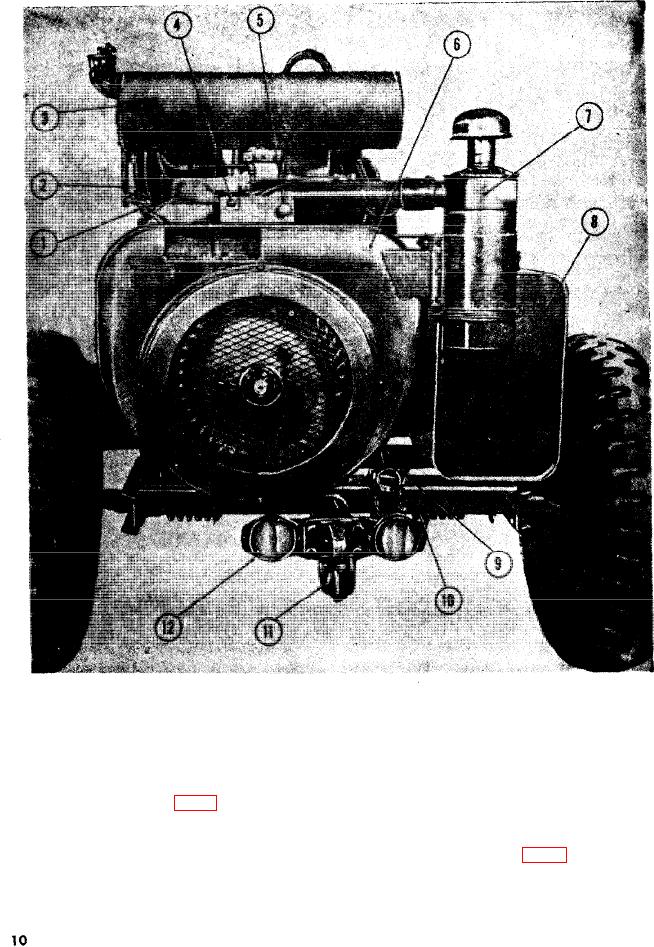
Ground rod holder
5
Choke control
1
Spark plug
10
Frame
6
Engine front end panel
2
Manifold assembly
11
Pintle hook
7
Air cleaner
3
12
Reflector
8
Fuel tank
4
Ignition switch
Engine front end panel.
reduces engine speed to idling; pulling
c. Throttle control (fig. 5).
it fully out permits the engine to op-
(1) Location. The throttle control (12) is
erate at governed speed.
located near the engine instrument
d. Vacuum gage (fig. 5).
panel.
(1) Location. The engine vacuum g a g e
(2) Purpose. The throttle control provides
(5) is located in the upper center of
a means of controlling the engine
the control panel (4).
speed. Pushing the throttle fully in