
TM 5-3825-270-23&P
0140
INSTALLATION
NOTE
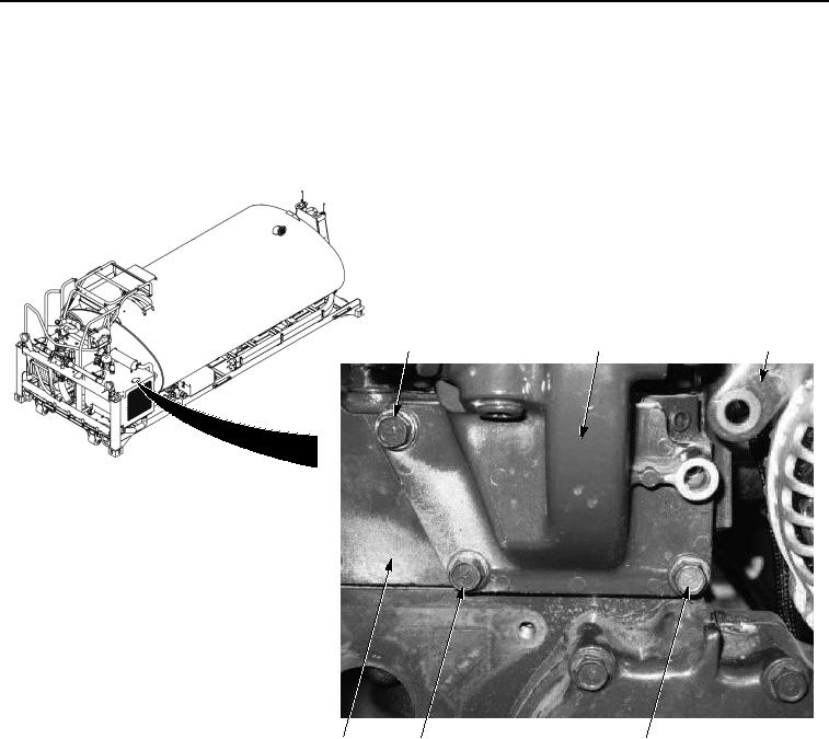
Perform Steps (1) through (5) if thermostat housing was removed.
1.
Install thermostat housing (Figure 8, Item 3) and gasket (Figure 8, Item 16) on cylinder head (Figure 8, Item
12) with three screws (Figure 8, Item 15).
15
3, 16
11
12
15
15
Figure 8. Thermostat and Housing Installation.
2.
Install bracket (Figure 9, Item 11) on thermostat housing (Figure 9, Item 3) and cylinder head (Figure 10, Item
12) with screw (Figure 9, Item 10).