
TM 5-3825-270-23&P
0140
REMOVAL - Continued
15
3, 16
11
12
15
15
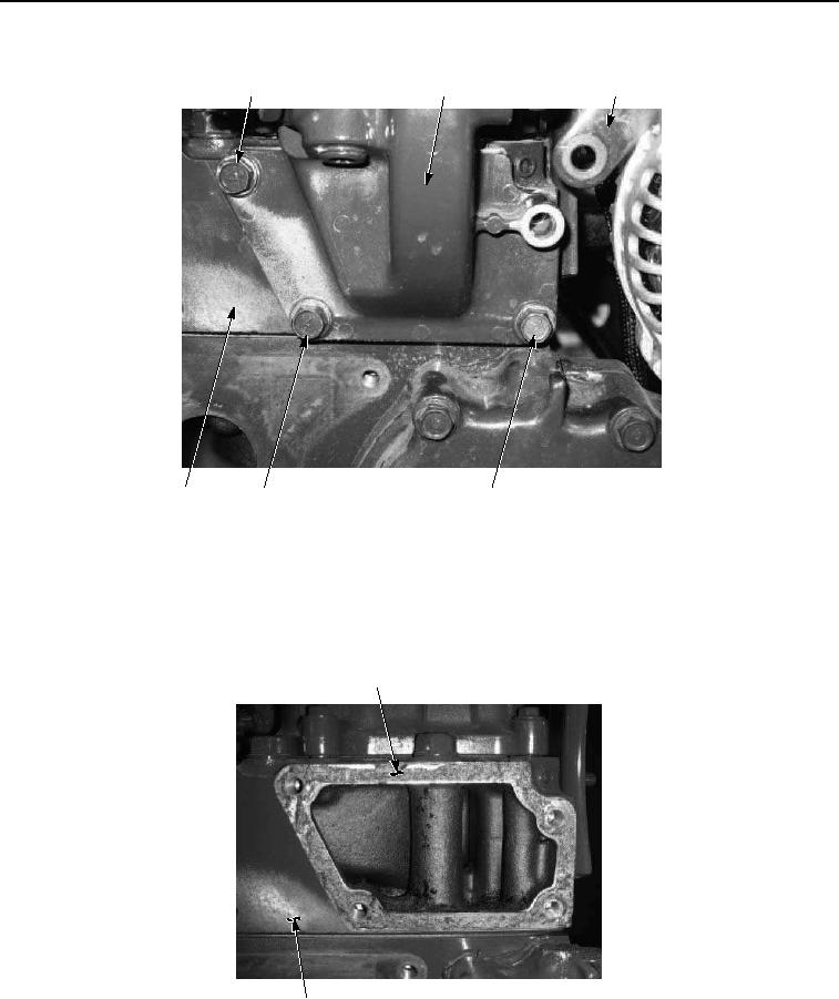
Figure 6. Thermostat and Housing Removal.
9.
Remove three screws (Figure 6, Item 15), thermostat housing (Figure 6, Item 3), and gasket (Figure 6, Item
16) from cylinder head (Figure 6, Item 12). Discard gasket.
10.
Remove any remaining gasket material from mating surface (Figure 7, Item 17) on cylinder head (Figure 7,
Item 12).
17
12
Figure 7. Thermostat and Housing Removal.
END OF TASK