
TM 5-3825-270-23&P
0138
INSTALLATION
NOTE
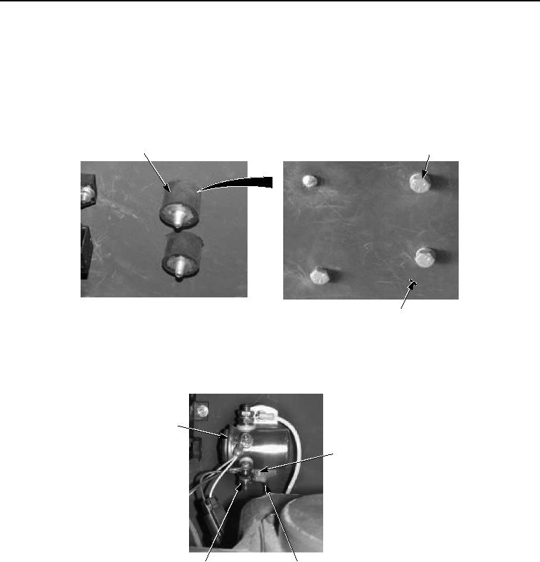
Perform Step (1) if isolator was removed.
All isolators are installed the same way. Top isolator shown.
1.
Install isolator (Figure 4, Item 16) on mounting surface (Figure 4, Item 23) with lockwasher (Figure 4, Item 22)
and screw (Figure 4, Item 21).
16
21, 22
23
Figure 4. Starter Relay Installation.
2.
Install starter relay (Figure 5, Item 13) on two isolators (Figure 5, Item 16) with lockwashers (Figure 5, Item 15)
and nuts (Figure 3, Item 14).
13
14, 15, 16
18, 19, 20
17
Figure 5. Starter Relay Installation.
NOTE
Route and install wires as noted prior to removal.
3.
Install red wire (Figure 5, Item 17) on stud (Figure 5, Item 20) with lockwasher (Figure 5, Item 19) and nut
(Figure 5, Item 18).
4.
Install white wire (Figure 6, Item 7) on stud (Figure 6, Item 6) with lockwasher (Figure 6, Item 5) and nut (Figure
6, Item 4).