
TM 5-3825-270-23&P
0128
INSTALLATION - Continued
11.
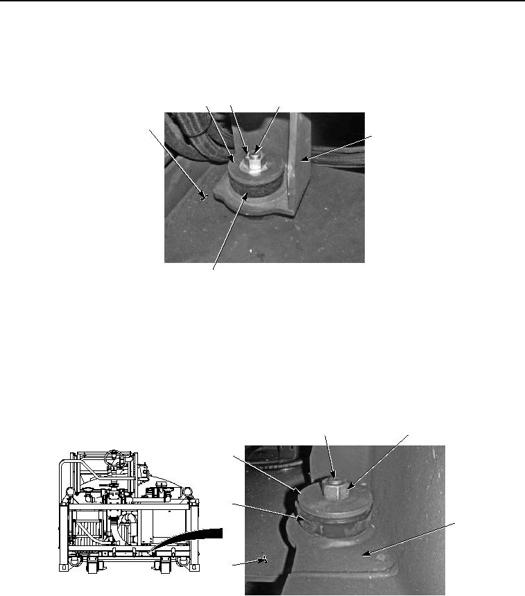
Secure rear engine mount bracket (Figure 25, Item 50) to frame (Figure 25, Item 44) with washer (Figure 25,
Item 49), screw (Figure 25, Item 48), upper isolator mount (Figure 25, Item 51), upper snubbing washer (Figure
25, Item 46), and locknut (Figure 25, Item 47). Tighten locknut to 150 lb-ft (203 NM).
46
47
48, 49
44
50
51
Figure 25. Engine Module Installation.
12.
Repeat Step (11) for other side.
NOTE
Both front engine mount bracket bushings are installed the same way. Right side shown.
13.
Secure front engine mount bracket (Figure 26, Item 43) to frame (Figure 26, Item 44) with washer (Figure 26,
Item 41), screw (Figure 26, Item 40), upper isolator mount (Figure 26, Item 45), upper snubbing washer (Figure
26, Item 39), and locknut (Figure 26, Item 42). Tighten locknut to 150 lb-ft (203 Nm).
40, 41
42
39
45
43
44
Figure 26. Engine Module Installation.
14.
Repeat Step (13) for left side.
NOTE
Route wiring as noted prior to removal.