
TM 5-3825-270-23&P
0127
INSTALLATION - Continued
NOTE
Install wire ties and cushion clips as required.
Route wire harnesses as noted prior to removal to ensure proper installation.
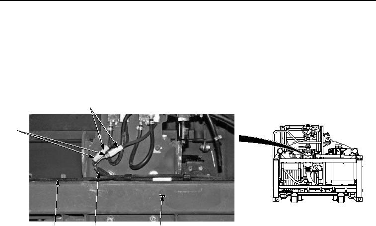
8.
Install air valve switch wire harness (Figure 9, Item 6) and work light wire harness (Figure 9, Item 7) on engine/
pump module (Figure 9, Item 5).
4
8
7
6
5
Figure 9. Engine/Pump Module Installation.
9.
Connect two air valve switch connectors (Figure 9, Item 4) to two air valve switch harness connectors (Figure
9, Item 8).
NOTE
Install cable ties and cushion clips as required.
10.
Install air line (Figure 10, Item 2) on oiler (Figure 10, Item 1) with clamp (Figure 10, Item 3).