
TM 5-3825-270-23&P
0120
INSTALLATION - Continued
8
10
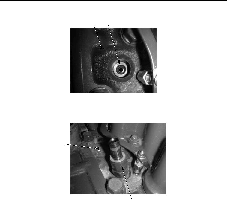
Figure 6. Injection Nozzle Assembly Installation.
3.
Install four injection nozzle assemblies (Figure 7, Item 9) in cylinder head (Figure 7, Item 8). Tighten to 37 to
50 ft-lb (50 to 68 Nm).
8
9
Figure 7. Injection Nozzle Assembly Installation.
4.
Install fuel tube (Figure 8, Item 3) on four injection nozzle assemblies (Figure 8, Item 7) with nuts (Figure 8,
Item 6). Tighten to 15 in-lb (20 Nm).