
TM 5-3825-270-23&P
0108
INSTALLATION - Continued
19.
Install white wire on positive terminal strip (Figure 8, Item 7) socket 18.
20.
Install white wire on positive terminal strip (Figure 8, Item 7) socket 7.
WARNING
Adhesives, solvents, and sealing compounds can burn easily, can give off harmful vapors,
and are harmful to skin and clothing. Keep away from open fire and use in well-ventilated
area. If adhesive, solvent, or sealing compound gets on skin or clothing, wash immediately
with soap and water. Failure to comply may result in injury or death to personnel.
21.
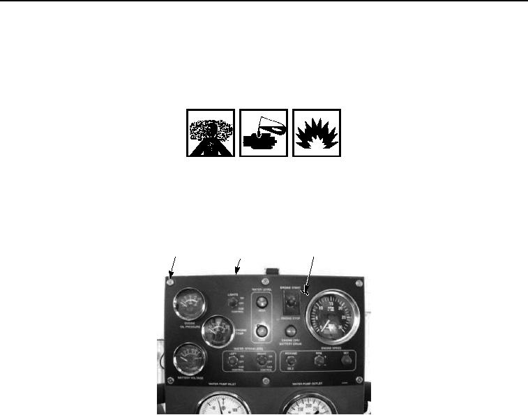
Apply sealant to the threads of six screws (Figure 9, Item 3).
5
6
3, 4
Figure 9. UPIK Wire Harness Installation.
22.
Install six washers (Figure 9, Item 4) and screws (Figure 9, Item 3) on main control box (Figure 9, Item 5) and
control panel (Figure 9, Item 6). Tighten six screws securely.
23.
Close control panel cover (Figure 10, Item 2) and secure with rubber t-handle (Figure 10, Item 1).