
TM 5-3825-270-23&P
0095
REMOVAL - Continued
7, 12
11
6
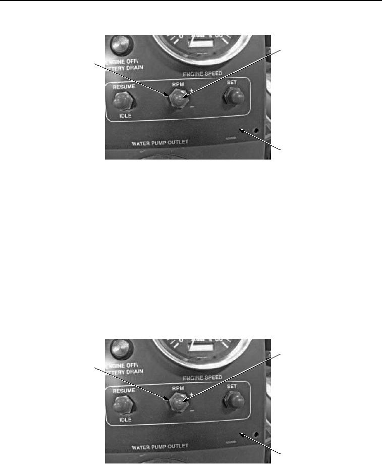
Figure 4. Main Control Panel Engine Speed RPM Switch Removal.
NOTE
Note position of main control panel engine speed RPM switch prior to removal to ensure
proper installation.
7.
Remove nut (Figure 4, Item 11) and main control panel engine speed RPM switch (Figure 4, Item 7) from
control panel (Figure 4, Item 6).
END OF TASK
INSTALLATION
NOTE
Install main control panel engine speed RPM switch as noted prior to removal.
1.
Install main control panel engine speed RPM switch (Figure 5, Item 7) on control panel (Figure 5, Item 6) with
nut (Figure 5, Item 11).
7, 12
11
6
Figure 5. Main Control Panel Engine Speed RPM Switch Removal.
2.
Install toggle switch seal (Figure 5, Item 12) on main control panel engine speed RPM switch (Figure 5, Item
7).