
TM 5-3825-270-23&P
0036
CONDITION/INDICATION
Does ENGINE TEMP gauge light illuminate?
DECISION
No - Replace ENGINE TEMP gauge. (WP 0097) Verify problem is solved. (Step 6 - Does ENGINE TEMP gauge
operate normally?)
Yes - Go to step 2. (Step 2 - Are 22 to 28 VDC present at ENGINE TEMP gauge harness connector, pin 6?)
STEP 2
Are 22 to 28 VDC present at ENGINE TEMP gauge harness connector, pin 6?
WARNING
Remove all jewelry such as rings, ID tags, bracelets, etc., prior to working on or around
vehicle. Jewelry and tools can catch on equipment, contact positive electrical circuits, and
cause a direct short, severe burns, or electrical shock. Failure to comply may result in injury
or death to personnel.
1.
Push in EMERGENCY STOP switch to off position. (TM 5-3825-270-10)
2.
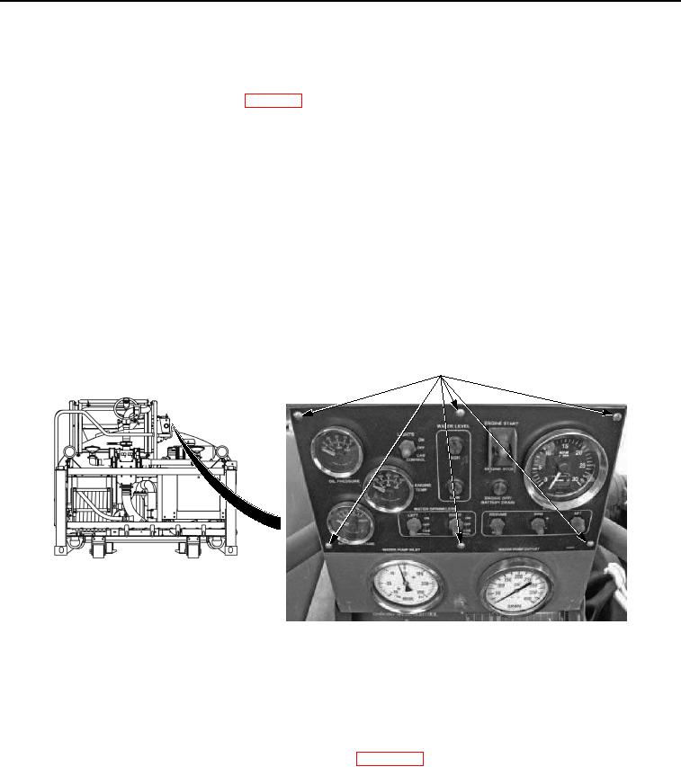
Remove six control panel faceplate screws.
CONTROL PANEL
FACEPLATE SCREWS
Figure 2. Control Panel Faceplate Screws - Step 2.
NOTE
Engine oil pressure, coolant temperature, and battery voltage control panel gauges have
identical harness connectors. Only one is shown for reference.
3.
Disconnect ENGINE TEMP gauge harness connector. (WP 0097)